Overview
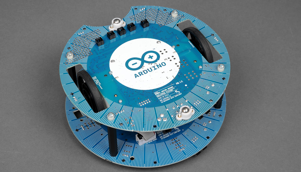
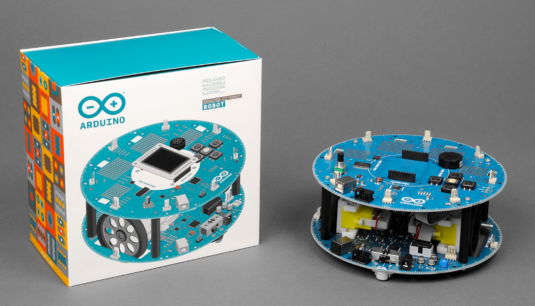
The Arduino Robot is the first official Arduino on wheels. The robot has two processors, one on each of its two boards. The?Motor Board?controls the motors, and the?Control Board?reads sensors and decides how to operate. Each of the boards is a full Arduino board programmable using the Arduino IDE.
Both Motor and Control boards are microcontroller boards based on the?ATmega32u4?(datasheet). The Robot has many of its pins mapped to on-board sensors and actuators.
Programming the robot is similar to the process with the Arduino Leonardo. Both processors have built-in USB communication, eliminating the need for a secondary processor. This allows the Robot to appear to a connected computer as a virtual (CDC) serial / COM port.
As always with Arduino, every element of the platform ? hardware, software and documentation ? is freely available and open-source. This means you can learn exactly how it's made and use its design as the starting point for your own robots. The Arduino Robot is the result of the collective effort from an international team looking at how science can be made fun to learn. Arduino is now on wheels, come ride with us!
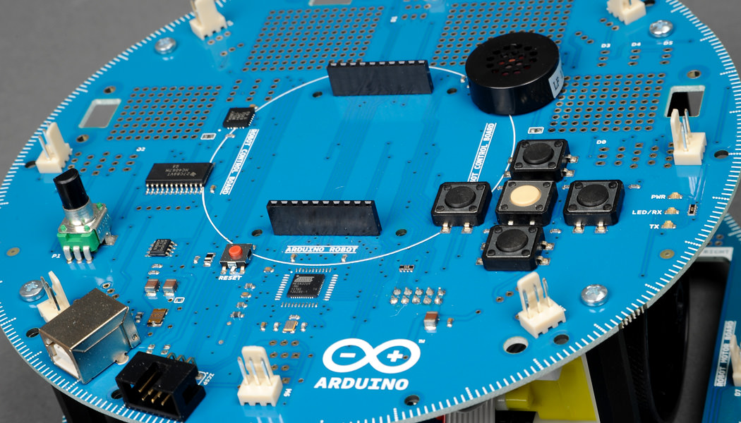
Control Board Summary
| Microcontroller |
ATmega32u4 |
| Operating Voltage |
5V |
| Input Voltage |
5V through flat cable |
| Digital I/O Pins |
5 |
| PWM Channels |
6 |
| Analog Input Channels |
4 (of the Digital I/O pins) |
| Analog Input Channels (multiplexed) |
8 |
| DC Current per I/O Pin |
40 mA |
| Flash Memory |
32 KB (ATmega32u4) of which 4 KB used by bootloader |
| SRAM |
2.5 KB (ATmega32u4) |
| EEPROM (internal) |
1 KB (ATmega32u4) |
| EEPROM (external) |
512 Kbit (I2C) |
| Clock Speed |
16?MHz |
| Keypad |
5 keys |
| Knob |
potentiomenter attached to analog pin |
| Full color LCD |
over SPI communication |
| SD card reader |
for?FAT16?formatted cards |
| Speaker |
8 Ohm |
| Digital Compass |
provides deviation from the geographical north in degrees |
| I2C?soldering ports |
3 |
| Prototyping areas |
4 |
Motor Board Summary
| Microcontroller |
ATmega32u4 |
| Operating Voltage |
5V |
| Input Voltage |
9V to battery charger |
| AA battery slot |
4 alkaline or?NiMh?rechargeable batteries |
| Digital I/O Pins |
4 |
| PWM Channels |
1 |
| Analog Input Channles |
4 (same as the Digital I/O pins) |
| DC Current per I/O Pin |
40 mA |
| DC-DC converter |
generates 5V to power up the whole robot |
| Flash Memory |
32 KB (ATmega32u4) of which 4 KB used by bootloader |
| SRAM |
2.5 KB (ATmega32u4) |
| EEPROM |
1 KB (ATmega32u4) |
| Clock Speed |
16?MHz |
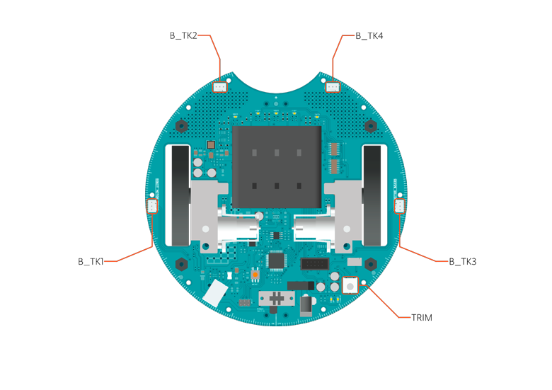
| Trimmer |
for movement calibration |
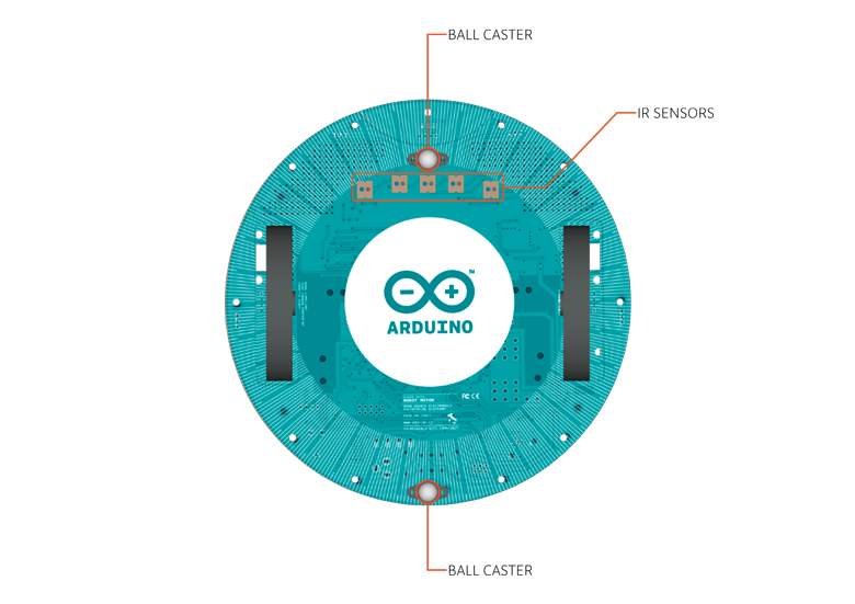
| IR line following sensors |
5 |
| I2C?soldering ports |
1 |
| Prototyping areas |
2 |
Schematic & Reference Design
EAGLE files for control and motor boards:?arduino-robot-reference-design.zip
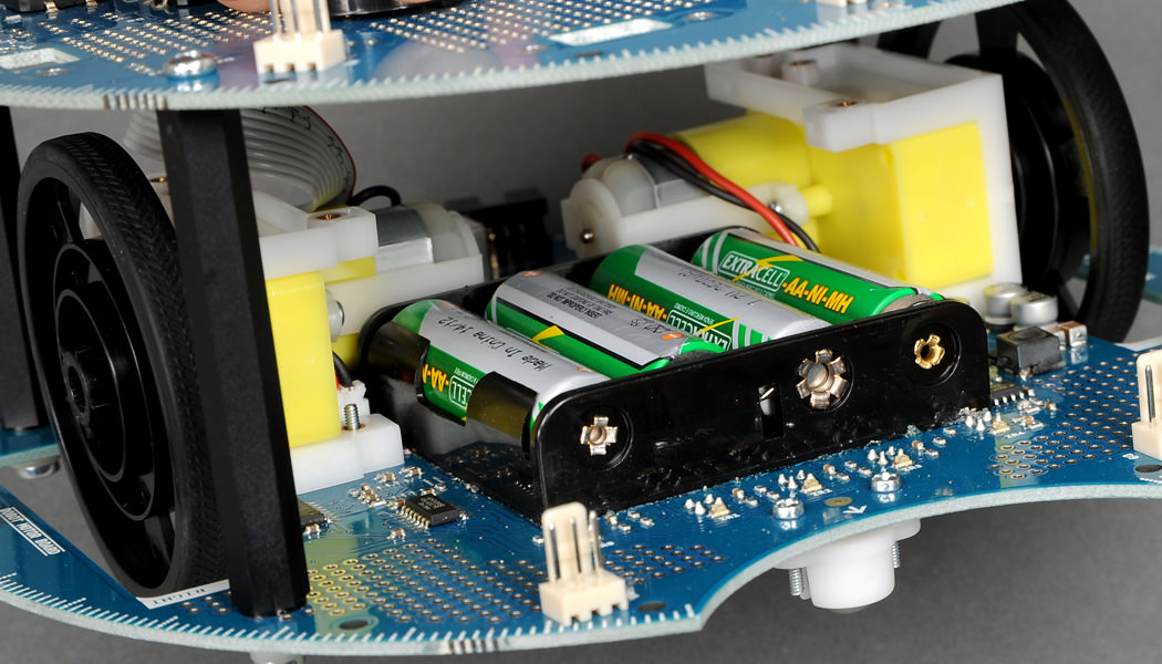
Power
The Arduino Robot can be powered via the USB connection or with 4 AA batteries. The power source is selected automatically.
The battery holder holds 4 rechargeable?NiMh?AA batteries.
NB : Do not use non-rechargeable batteries with the robot
For safety purposes, the motors are disabled when the robot is powered from the USB connection.
The robot has an on-board battery charger that requires 9V external power coming from an AC-to-DC adapter (wall-wart). The adapter can be connected by plugging a 2.1mm center-positive plug into the Motor Board's power jack. The charger will not operate if powered by USB.
The Control Board is powered by the power supply on the Motor Board.
Memory
The?ATmega32u4?has 32 KB (with 4 KB used for the bootloader). It also has 2.5 KB of SRAM and 1 KB of EEPROM (which can be read and written with the?EEPROM library).
The Control Board has an extra 512 Kbit EEPROM that can be accessed via?I2C.
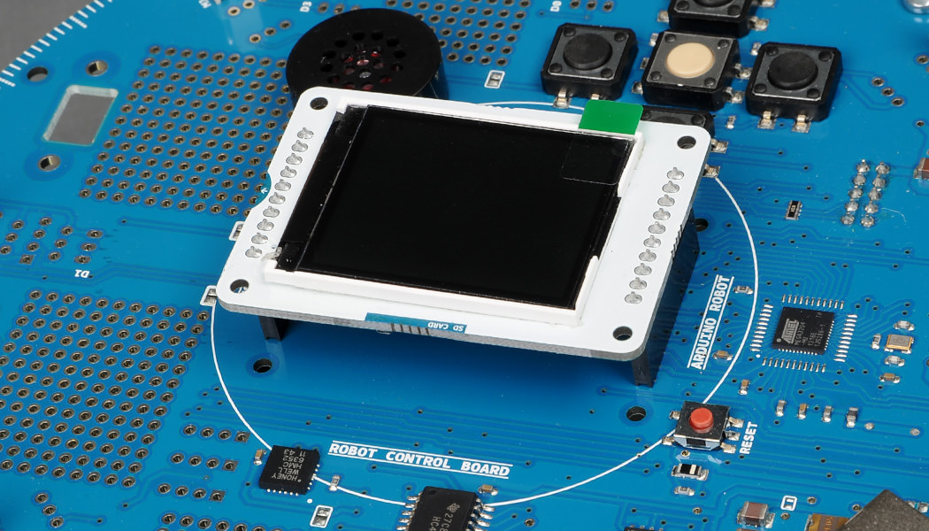
There is an external SD card reader attached to the GTFT screen that can be accessed by the Control Board's processor for additional storage.
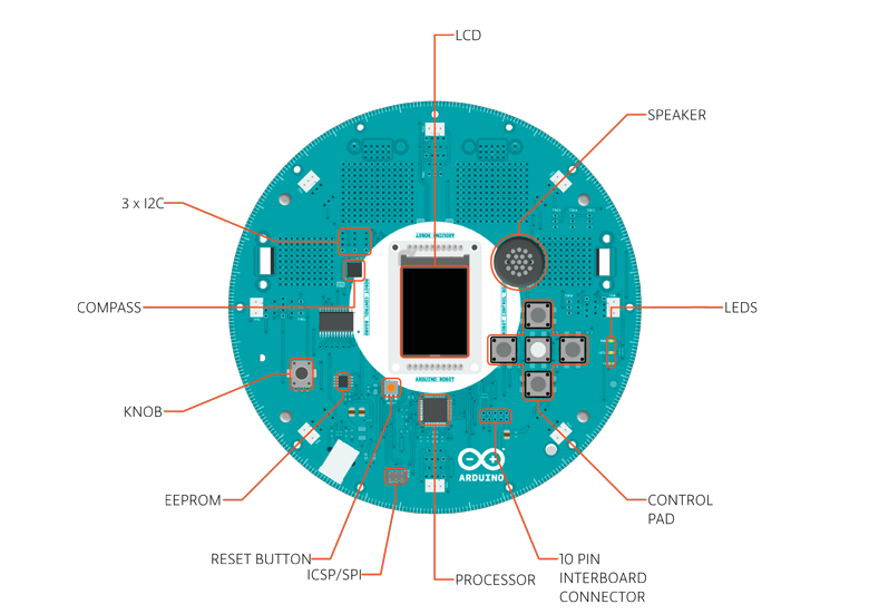
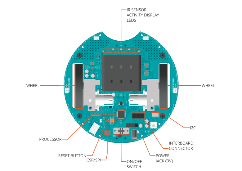
Input and Output
The Robot comes with a series of pre-soldered connectors. There are a number of additional spots for you to install additional parts if needed.
All the connectors are labelled on the boards and mapped to named ports through the?Robot library?allowing access to standard Arduino functions. Each pin can provide or receive a maximum of 40mA at 5V.
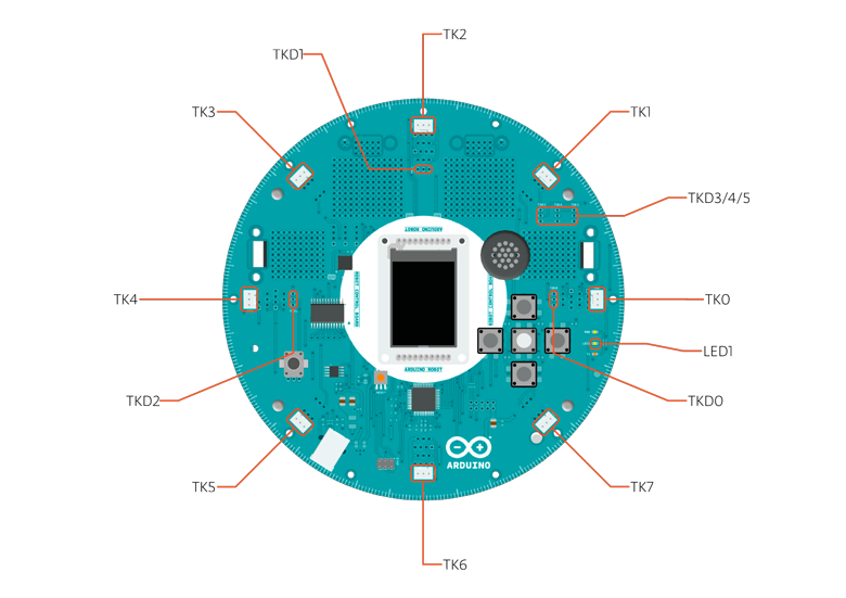
Some pins have specialized functions :
- Control Board?TK0?to?TK7: these pins are multiplexed to a single analog pin on theControl Board's microprocessor. They can be used as analog inputs for sensors like distance sensors, analog ultrasound sensors, or mechanical switches to detect collisions.
- Control Board?TKD0?to?TKD5: these are digital I/O pins directly connected to the processor, addressed usingRobot.digitalRead()?and?Robot.digitalWrite)?functions. Pins?TKD0?to?TKD3?can also be used as analog inputs withRobot.analogRead()
Note: if you have one of the first generation robots, you will see that the TKD* pins are named TDK* on the Robot's silkscreen. TKD* is the proper name for them and is how we address them on the software.
- Serial Communication: The boards communicate with each other using the processors' serial port. A 10-pin connector connects both boards carries the serial communication, as well as power and additional information like the battery's current charge.
- Control Board SPI: SPI is used to control the GTFT and SD card. If you want to flash the processor using an external programmer, you need to disconnect the screen first.
- Control Board?LEDs: the Control Board has three on-board?LEDs. One indicates the board is powered (PWR). The other two indicate communication over the USB port (LED1/RX and TX).?LED1?is also accessible via software.
- Both boards have?I2C?connectors available: 3 on the Control Board and 1 on the Motor Board.
Control Board Pin Mapping
| ARDUINO LEONARDO |
ARDUINO ROBOT CONTROL |
ATMEGA 32U4 |
FUNCTION |
REGISTER |
| D0 |
RX |
PD2 |
RX |
RXD1/INT2 |
| D1 |
TX |
PD3 |
TX |
TXD1/INT3 |
| D2 |
SDA |
PD1 |
SDA |
SDA/INT1 |
| D3# |
SCL |
PD0 |
PWM8/SCL |
OC0B/SCL/INT0 |
| D4 |
MUX_IN A6 |
PD4 |
? |
ADC8 |
| D5# |
BUZZ |
PC6 |
??? |
OC3A/#OC4A |
| D6# |
MUXA/TKD4 A7 |
PD7 |
FastPWM |
#OC4D/ADC10 |
| D7 |
RST_LCD |
PE6 |
? |
INT6/AIN0 |
| D8 |
CARD_CS A8 |
PB4 |
? |
ADC11/PCINT4 |
| D9# |
LCD_CS A9 |
PB5 |
PWM16 |
OC1A/#OC4B/ADC12/PCINT5 |
| D10# |
DC_LCD A10 |
PB6 |
PWM16 |
OC1B/0c4B/ADC13/PCINT6 |
| D11# |
MUXB |
PB7 |
PWM8/16 |
0C0A/OC1C/#RTS/PCINT7 |
| D12 |
MUXC/TKD5 A11 |
PD6 |
? |
T1/#OC4D/ADC9 |
| D13# |
MUXD |
PC7 |
PWM10 |
CLK0/OC4A |
| A0 |
KEY D18 |
PF7 |
? |
ADC7 |
| A1 |
TKD0 D19 |
PF6 |
? |
ADC6 |
| A2 |
TKD1 D20 |
PF5 |
? |
ADC5 |
| A3 |
TKD2 D21 |
PF4 |
? |
ADC4 |
| A4 |
TKD3 D22 |
PF1 |
? |
ADC1 |
| A5 |
POT D23 |
PF0 |
? |
ADC0 |
| MISO |
MISO D14 |
PB3 |
? |
MISO,PCINT3 |
| SCK |
SCK D15 |
PB1 |
? |
SCK,PCINT1 |
| MOSI |
MOSI D16 |
PB2 |
? |
MOSI,PCINT2 |
| SS |
RX_LED D17 |
PB0 |
? |
RXLED,SS/PCINT0 |
| TXLED |
TX_LED |
PD5 |
? |
? |
| HWB |
? |
PE2 |
? |
HWB |
Motor Board Pin Mapping
| ARDUINO LEONARDO |
ARDUINO ROBOT CONTROL |
ATMEGA 32U4 |
FUNCTION |
REGISTER |
| D0 |
RX |
PD2 |
RX |
RXD1/INT2 |
| D1 |
TX |
PD3 |
TX |
TXD1/INT3 |
| D2 |
SDA |
PD1 |
SDA |
SDA/INT1 |
| D3# |
SCL |
PD0 |
PWM8/SCL |
OC0B/SCL/INT0 |
| D4 |
TK3 A6 |
PD4 |
? |
ADC8 |
| D5# |
INA2 |
PC6 |
??? |
OC3A/#OC4A |
| D6# |
INA1 A7 |
PD7 |
FastPWM |
#OC4D/ADC10 |
| D7 |
MUXA |
PE6 |
? |
INT6/AIN0 |
| D8 |
MUXB A8 |
PB4 |
? |
ADC11/PCINT4 |
| D9# |
INB2 A9 |
PB5 |
PWM16 |
OC1A/#OC4B/ADC12/PCINT5 |
| D10# |
INB1 A10 |
PB6 |
PWM16 |
OC1B/0c4B/ADC13/PCINT6 |
| D11# |
MUXC |
PB7 |
PWM8/16 |
0C0A/OC1C/#RTS/PCINT7 |
| D12 |
TK4 A11 |
PD6 |
? |
T1/#OC4D/ADC9 |
| D13# |
MUXI |
PC7 |
PWM10 |
CLK0/OC4A |
| A0 |
TK1 D18 |
PF7 |
? |
ADC7 |
| A1 |
TK2 D19 |
PF6 |
? |
ADC6 |
| A2 |
MUX_IN D20 |
PF5 |
? |
ADC5 |
| A3 |
TRIM D21 |
PF4 |
? |
ADC4 |
| A4 |
SENSE_A D22 |
PF1 |
? |
ADC1 |
| A5 |
SENSE_B D23 |
PF0 |
? |
ADC0 |
| MISO |
MISO D14 |
PB3 |
? |
MISO,PCINT3 |
| SCK |
SCK D15 |
PB1 |
? |
SCK,PCINT1 |
| MOSI |
MOSI D16 |
PB2 |
? |
MOSI,PCINT2 |
| SS |
RX_LED D17 |
PB0 |
? |
RXLED,SS/PCINT0 |
| TXLED |
TX_LED |
PD5 |
? |
? |
| HWB |
? |
PE2 |
? |
HWB |
Communication
The Robot has a number of facilities for communicating with a computer, another Arduino, or other microcontrollers. The?ATmega32U4?provides UART TTL (5V) serial communication, which is available on digital the 10-pin board-to-board connector. The 32U4 also allows for serial (CDC) communication over USB and appears as a virtual com port to software on the computer. The chip also acts as a full speed USB 2.0 device, using standard USB COM drivers.?On Windows, a .inf file is required. The Arduino software includes a serial monitor which allows simple textual data to be sent to and from the Robot board. The RX (LED1) and TX?LEDs?on the board will flash when data is being transmitted via the USB connection to the computer (but not for serial communication between boards).
Each one of the boards has a separate USB product identifier and will show up as different ports on you IDE. Make sure you choose the right one when programming.
The?ATmega32U4?also supports?I2C?(TWI) and SPI communication. The Arduino software includes a Wire library to simplify use of the?I2C?bus; see the?documentation?for details. For SPI communication, use the?SPI library.
Programming
The Robot can be programmed with the Arduino software (download). Select "Arduino Robot Control Board" or "Arduino Robot Motor Board" from the?Tools > Board?menu. For details, see the?getting started page?and?tutorials.
The?ATmega32U4?processors on the Arduino Robot come preburned with a?bootloader?that allows you to upload new code to it without the use of an external hardware programmer. It communicates using the?AVR109?protocol.
You can bypass the bootloader and program the microcontroller through the ICSP (In-Circuit Serial Programming) header; see?these instructions?for details.
Automatic (Software) Reset and Bootloader Initiation
Rather than requiring a physical press of the reset button before an upload, the Robot is designed in a way that allows it to be reset by software running on a connected computer. The reset is triggered when the Robot's virtual (CDC) serial / COM port is opened at 1200 baud and then closed. When this happens, the processor will reset, breaking the USB connection to the computer (meaning that the virtual serial / COM port will disappear). After the processor resets, the bootloader starts, remaining active for about 8 seconds. The bootloader can also be initiated by double-pressing the reset button on the Robot. Note that when the board first powers up, it will jump straight to the user sketch, if present, rather than initiating the bootloader.
Because of the way the Robot handles reset it's best to let the Arduino software try to initiate the reset before uploading, especially if you are in the habit of pressing the reset button before uploading on other boards. If the software can't reset the board you can always start the bootloader by double-pressing the reset button on the board.?A single press on the reset will restart the user sketch, a double press will initiate the bootloader.
USB Overcurrent Protection
Both of the Robot boards have a resettable polyfuse that protects your computer's USB ports from shorts and overcurrent. Although most computers provide their own internal protection, the fuse provides an extra layer of protection. If more than 500 mA is applied to the USB port, the fuse will automatically break the connection until the short or overload is removed.
Physical Characteristics
The Robot is 19cm in diameter. Including wheels, GTFT screen and other connectors it can be up to 10cm tall.
To Learn More
See also:?getting started with the Arduino Robot?and?the Robot's library pages.
Our warranty/ return / exchange policy is very simple. If the item we sent you is defective when you received the shipment from us (NOT AFTER USE), you can report to us by email for return / exchange / refund arrangement.
Request(s) for return or exchange and report(s) of missing or damaged part(s) must be received within 30 days of your receipt of merchandise(s). We reserves the rights to entertain requests received thereafter.
Items returned must be in as-new conditions with the packing slips, manuals, accessories and all other items intact in original packaging. Returned merchandise must be received from our customer before we will process and ship out any replacement. All merchandise should be returned to us by shipping carriers with safe method which provides proof of shipment (just in case your item does not reach us. so you can check with your local shipping carrier.) We will not responsible for the lost of returned merchandise in shipping.
Shipping and handling charges for all orders are non-refundable, as we have paid the Post Office to send the shipment and the Post Office will NOT refund the postage cost back to us after they processed the shipment. Customer will be responsible for the return shipping cost to send return back to us. For returned merchandise that is found to be genuinely defective, we ship out replacement for free (we pay for the replacement shipping cost) and will not charge additional shipping and handling fees.
We reserves the right to return merchandise to its customer and not refund money, if we in our opinion deem that the merchandise has been used, crashed, abused, misused or modified in any form, or has been damaged by water, dust, or other contaminants.
*** All items are tested by manufactures to make sure they are working properly before we ship them to our customers.
*** Please inspect the product when you received the shipment, identified any issue and report to us BEFORE you try to fly / use it. Please also check over the product (especially the helicopters and air planes) and make sure they are all good every time before use (or taking to the air).
*** Return / exchange / refund is not allowed if the item has been used or flew. Please understand that RC helicopters and airplanes can crash if mistake made or you do not know how to fly, any kind of crash or hard landing may caused damage(s) to the helicopter or plane. We have no control over your flying skill, behavior or the conditions you have chosen to fly in. We tested all products before shipment as we stated above, if you have any problem with the aircraft or other product(s) you ordered from us, please report it at the time when you received the shipment (not after use please).
*** If you used / flew the product, or crashed product, no matter what the reason. We are sorry but we can not be responsible for your crash or use. Hobbypartz.com will not be responsible for incidental or consequential damages including bodily injuries and property damages arising from the use of any product(s) that it sells. Hobbypartz.com reserves the right to refuse service to anyone. Remote controlled products and accessories can be very dangerous. Please read the operating manual before use. We have no control over the correct use, installation, application, or maintenance of our products, no liability shall be assumed nor accepted for any damages, losses or costs resulting from the use of the products. Any claims arising from the operating, failure or malfunctioning etc. will be denied. We assume no liability for personal injuries, property damages or consequential damages resulting from our products.
*** These terms applied to all sales made from our website, email, phone, or fax. If you do not agree to our terms, please do not make the order.
We reserves the right to amend this policy without further notification(s).
To experience 5-Star Customer Service & Tech Support from HobbyPartz.com, visit us at RCDiscuss.com


")